Star Trek LX-8: EPROM Labels

On Feb 15, 2023; ingo333 of Pinside released a bug fix update to the Williams Star Trek Pinball machine from 1993. You can download his rom patcher from: his proton drive for free. Included in the change list is the incorporation of the Lamp matrix patch to make it it more compatible with LEDs and this feature is controlled by an Feature Adjustment in the game’s settings. There are several other improvements including randomized shuttlecraft caves which are clearly documented in the STNG_LX8.pdf inside his archive.

In celebration of their work; I created a set of EPROM labels to cover the eprom window. I’ve decided to release the labels for free personal use. Enjoy!

Printed on 1×2.75″ mailing label stock. Compatible with Avery 5351.

To install the new rom;

  1. power off Pinball Machine.
  2. Unlock Backglass and place in a safe place to prevent breakage. Key for the lock should be in the coin door of your machine.
  3. Open service door and locate CPU board on left hand side. You shouldn’t need to remove speaker panel to install new rom.
  4. Remove AA batteries to drain game settings. The reason why is explained in Chapter 4 (Troubleshooting) of their manual.
  5. Using a chip puller; carefully remove the existing rom on the CPU board. Note the orientation of the existing rom. It should be with the notch facing the right hand side of the game. Set old rom aside incase you want to back out this upgrade.
  6. Carefully install the new LX-8 rom chip in the same orientation. The notch should face the right hand side of the game. Watch during installation to make sure no pins are bent as the rom is installed in the socket. The pins can bend under the package so best to do it with a flash light.
  7. Inspect newly installed rom to insure no pins are bent and that you didn’t offset during install.
  8. Re-install batteries. We’d suggest taking the time to install a fresh set so that you don’t have the batteries leak.
  9. Verify the notch orientation a final time.
  10. Once you’re sure it’s installed properly; power up the game. You should be greeted with a “Factory Reset” message.
  11. Open coin door and enter service mode using the buttons. You should see LX-8 displayed on the DMD.

    Adjust settings as desired based upon STTNG_LX8.pdf manual in the proton drive archive.
  12. Close service door, re-install backglass, and return the backglass lock to the coin door.

Announce: Star Rollover LED boards

We are pleased to make a delayed announcement of a product which we’ve had in stock for almost a year. This Star Rollover LED board fits on the underside of your Playfield under a Star rollover assembly and will bathe the Star Insert is lower power LED light. With this product you can replace the inefficient horizontal lamp socket and incandescent light bulb with this board:
Star Rollover
Each board provides 4 natural white LEDs in a non-polarized light from either a 6.3V source. Because the board has a built-in rectifier bridge; you can supply power from both a 6.3VAC GI circuit or ~6.3VDC controlled insert. You can even control the brightness via a microcontroller PWM signal or from one of the new DIY control systems such as the PROC or its PD-LED driver board.

The design also features a brightness resistor at R5 to allow you to dial the brightness to your desired level. A hole in the center of our PCB allows the actuator to work from the insert to a standard Leaf switch typically under the insert.

A typical installation may require a set of #6-32 x 0.25 inch wood screws so you can bolt it to the back of the playfield under the star rollover insert. Electrical installation is super simple; simply solder the GI connection from the old horizontal lamp socket to the JGI connection, or jump to the nearest GI socket as we did in our machine below. Here is an example installation we did on our Star Trek: The Mirror Universe custom pinball machine.


Source: My Star Trek: The Mirror Universe custom machine

This populated PCB is available for immediate shipping in Our Online store @ http://pinball-mods.com/oscom/modifications-do-it-yourself-star-rollover-led-p-17.html

EagleCAD Tutorial: Custom shaped PCBs

As seen in the Worklogs for the Star Trek: Mirror Universe Pinball project; Making custom shaped PCBs in EagleCad isn’t all that difficult. With a CAD file; one can make some pretty unique shapes to fit the project you’re working on. This tutorial aims to show just how easy it to create the perfect shaped PCB. The Author used this technique to create custom LED boards in the Mirror Universe project which replaced all the Switched Illumination sockets on the underside of the Playfield.

Pre-Requisites:

  1. EagleCad 5.11 or higher (tutorial written for 5.11).
  2. DXF2SCR from micromagic systems. (It’s Free and Awesome)
  3. A DXF file to convert. Scroll down for a .ZIP file containing files used in this Tutorial.
  4. About 10 minutes to do your first PCB outline.

Making the PCB shape

Please click the pictures below to be taken to a higher rez screen capture/picture.

1) The toughest part of this tutorial is creating the CAD file (DXF) which will serve as an input to the DXF2SCR tool. The author uses the Free  GPLed version of QCAD to create DXF files. Teaching QCAD is beyond the scope of this document; but the basic principle is that you want to create the outline of the PCB in CAD via a series of curves or lines. Make sure you put in any mounting holes you want … and maybe even some documentation layers; like a center line or critical component locations. This allows your PCB to be “exact” without having to move holes, lines, or arcs in EagleCad.

Once you have the CAD (DXF) file; you can proceed to covert the file using the DXF2SCR tool. Start by opening the tool and selecting the input DXF file and the output .scr file. The SCR file is used later to “draw” on a blank PCB canvas. More on that in a bit. Make sure you match the units in which you created the DXF file. In my case; I almost always use inches. At this point I basically leave everything else at defaults of 1mil (0.001 inches) line widths and no offset. I leave the line with at 1mil because I can change the width in eaglecad based upon whatever I’m trying to accomplish. For much of the file; it’ll be an outline – and most people recommend you leave the outline as a “hairline” so the fab house doesn’t “charge” you for the additional 8mil width of the outline.  Once you have the setup complete; click the Convert button on the left.

PCB Tutorial: DXF2SCR screen shots

If the conversion is successful; you should see the number of lines, arcs, circles, converted along with a Complete message. If you get that, you can move on to the next step.

2) I start by opening EagleCad and Selecting File/New/Board… This gives me a blank canvas to create the outline on. I’m fairly sure I’ve done this on an already created board; you just have to be careful how you move the outlines and such with components are in the way. By far tho; it’s easiest that you either create the Schematic after the PCB outline, or at least make sure you don’t place parts “inside” the normal rectangle when creating the PCB from schematic.
You need to run the script created in step 1 above. This is done from the File / Script… dialog. Select the SCR you created in step 1 (or in our case rollover2k.scr) and hit open.

PCB Tutorial: Run Script

3)At this point EagleCad should begin executing the script drawing your arcs/lines/circles on the  Dimension layer (layer 20).

PCB Tutorial: Custom Shaped PCB

At this point you should begin to move the documentation shapes to either tDoc or bDoc and then later move them to tSilk / bSilk if necessary. You want to leave the outline and any mounting holes as 20 Dimension Layer… as that is what the gerber generator uses to generate the .oln file when you commit this design to the PCB Fab houses like OSHPark.

If you do transfer some of the lines to a silkscreen layer or even a copper layer; you should remember to change it’s width to the minimum tolerance allowed by your FAB house. In the case of a 2layer OSHPark file… it’s probably 8mils (0.008 inch).

With the steps outline above; you can basically use the CAD file as an input to even align LEDs on a evenly spaced spoke pattern or really any desirable orientation.

I’m providing the input files here for you to follow along with the steps above. Download it here:
Shaped PCB Tutorial Files

This PCB outline was used in the Star Trek: Mirror Universe as the GI lighting for the Star Rollovers. The star plunger fits inside the center hole and the two holes on the side provide mounting to the underside of the playfield.  These PCBs light the Rollover from the underside with Red LEDs.


Hope this tutorial helps!
John

Star Trek: The Mirror Universe will be at Texas Pinball Fesitival

Phase 1 of the Star Trek Mirror Universe project is complete and will be on display at this year’s Texas Pinball Festival.

You can visit the details here on this blog… or visit the worklogs at KLOV forums or Pinside forums.

Give me a thumbs up Karma Point or Reputation point when visiting these forums.

Star Trek: The Mirror Universe Pinball – Cabinet work (Part 3)

Previous work on this Cabinet: part 1 and 2

Now my attention turns to the stenciling of the side cabinet. First color… yellow:
Star Trek: Mirror Cabinet

Star Trek: Mirror Cabinet

Star Trek: Mirror Cabinet

Star Trek: Mirror Cabinet

Once the yellow dried overnight; I pulled the stencil up:
Star Trek: Mirror Cabinet

Yeap; that’s right… The use of the waterslide decal came back and bit me in the butt. The stencil pulled the toner right off label.
Star Trek: Mirror Cabinet

:sigh:

After many choice explicatives; I decided there wasn’t much I could do now… so I went ahead and continued stenciling the grey; opting to see what (if anything) the Enterprise would cover. Ofcourse; I designed the decal location to be where the Klingons were; so I knew it wouldn’t cover jack… but it made me feel better. I also figured if the next stencil pulled up more; I could fix it once and be done.

Down goes the Enterprise stencil..
Star Trek: Mirror Cabinet

This time I left the protective backing on the section which went over the waterslide decal.
I sprayed the grey primer and let it dry overnight. The backing protect the label; so I proceeded to cover the paper areas with the black stain to match the color of the cabinet. I then re-airbrushed to blend the new black with the background image. I then re-sprayed the holographic flake and clear coat as best I could with airbrush.
Star Trek: Mirror Cabinet

Star Trek: Mirror Cabinet
Good as new? no. but, not too bad I guess.

Now for the orange stencil.
Star Trek: Mirror Cabinet

The orange wasn’t Red enough for my Nacelles… so I sprayed them with cherry red.
Star Trek: Mirror Cabinet

And finally; the blue phasers:
Star Trek: Mirror Cabinet

Ofcourse; the blue phasers crossed over the nebula – I had to use some of the stencil to prevent paint bleed. At this point more toner came off; so I had to do some more repair.

The result:
Star Trek: Mirror Cabinet

I’m 100% happy with the blue phasers; they tend to not show up well on the black without a grey border. Not sure what if anything I’m going to do.

Star Trek: The Mirror Universe Pinball – Head work (Part 4)

Previous work on this Head: part 1, 2, and 3

A couple of days ago; my custom stencils came in from TwistedPins. I started with the head because it was still on the hydraulic table from the fan installation. I decided I wanted to use the same head stencils as the original bally; just change up the colors a bit.

I started by laying down the yellow stencil:

At this point; an improvement I’d suggest to these stencils is that for the first layer… the “red” covers should be removed. IE the planetoids shouldn’t have any masks “inside” the oval shapes. That way you lay down a solid color and the second color (red) goes over the yellow so there are no registration offsets. This is what I did; I went ahead and removed all the squiggly shapes from the planetoids.

With the stencil ready; I taped off the surround areas with newspaper and put down some grey primer. This was done mainly to get the “grey” which I had chosen for the enterprise. Yellow generally goes over light grey than black so I sprayed everything.

I waited overnight for the grey primer to cure then masked off the enterprise grey and sprayed down some “Gold yellow” spray paint. I decided to use spray paint as it is easier to clean up than trying to spray the sign lettering enamel I used for the Bally Star Trek playfield repair many years ago.

I let the yellow dry about an hour before carefully removing the masking. Here’s how the first stencil turned out:

Another night time cure to let the paint harden before I put down the red-orange stencil. I decided I wanted the planetoid to be the same colors as original. The difference was in the Enterprise as you’ll see in a moment. I sprayed the planets and then the Enterprise-shadows as “Driver blue”.

I let the orange/blue combo cure in the TX sun for a few hours; then removed the masking.
The Result:

There were some slight registration issues with the blue and grey; but really not that bad. Again; If it were me; I’d have created the stencils with the entire Enterprise in “yellow” and then have the “red” overlay cover the yellow to avoid the registration issues. I’m guessing TwistedPin did the stencils that way so someone could just do a single color… but really; the Red fades long before the yellow; so in my mind the yellow stencil should cover all the areas Red+yellow.

Anyway; I’m digging the custom Enterprise colors. Thoughts?

Bally (AS-2518) Audio Card tester

For the past week or so; I’ve been working on the Audio solution for the Star Trek: Mirror Universe project. I’ve decided I want to combine a Raspberry Pi with the guts of a Bally AS-2518-32 soundcard. These cards are not yet rare; but the PROMs and the 4bit counter on them are rare. As a result; I’m going to be trying my luck with the first Complex Programmable Logic Device (CPLD) project I’ve ever embarked on. More on that later tho.

Given I’ve designed a replacement sound card out of new components; I wanted the ability to test the card outside of the machine… because I don’t want to risk burning up a perfectly good Bally CPU board with a risky design.

I spent quiet a bit of time looking at the schematics of the AS-2518 Bally sound cards to understand it’s functionality so it can be duplicated. The result is that I decided to design simple micro-controller-based tester which would sequence my new design thru all 32 tones generated by the on-board logic.  Since I already had a Arduino Nano (purchased from FRYs) for the Pinball Nixie Display project – I re-purposed it for the Pinball Audio Tester.

I began by rewiring the cables for the Audio board as follows:

J1
(Audio)

Arduino
Nano (PAD)

Color

Cable

NAME
(AUDIO)

12

D2

Orange

1

SOL_E

11


<KEY>

10


9


8

D8

Yellow

2

sol_bus_sel

7


NC

6

GND

Bare

2

BARE(GND)

5

+5V

Red

2

+5v

4

D11

purple

2

SOL_D

3

D12

brown

2

SOL_C

2

D13

grey

2

SOL_B

1

D7

blk

2

SOL_A

I’ve decided to share the Source code so that other Pinball hackers can take advantage of my work. You can download the source code from here:

PinAudioTester.ino Rev 0.1

The source is simple and should be easy to understand – please consider sharing any improvements you decide to make.

To power the Arduino and the soundcard; I created a 4pin Power cable which plugs into my debug ATX powersupply with color-coded aligator clips. I attach the Red (+5V) to the TP1 test point, Yellow (+12V) to the ?TP3? testpoint, and Ground (Black) to the TP2 testpoint. The design does not currently test the 43V to 12V linear supply as ATX doesn’t output that high of a voltage.

I’ve tested the source on my original AS-2518-32 sound card and it outputs 30 tones and two silences as implemented in the pROM. I now await the new soundcard PCBs from OSHPark to do some final testing.

Star Trek: The Mirror Universe Pinball – Head work (Part 3)

As Seen in part 1 and 2; I’ve been working on the cabinet for the Star Trek Mirror Universe.

This past weekend; I intended to wrap up the Impulse Engine modification to the Mirror Universe pinball head. Unfortunatly it spilled over to Monday; mainly because I couldn’t get my Laser cutter into a completely operational state. 🙁

Anywho; The intent was to make the vent holes to look like the Enterprise’s Impulse Engine. To do this I created a stencil using the same scale and rendering as before. Since My laser cutter only has a 12×24 table; I had to only do 1/2 the stencil opting to flip it for the opposite side. Here’s the stencil I created:

I laser cut this out of dry erase poster board and sprayed it lightly with some stencil spray adhesive. Here it is positioned for the left Impulse Engine vent:

Since I didn’t have any grey spray paint on hand… and it was near or after midnight; I opted to spray with primer grey:

I then flipped the stencil (after the primer had dried for a couple of hours) and sprayed the other side with light stencil adhesive and then grey primer:

Now I needed to do some shading of the upper piece; So I used the drop pieces cut from the stencil as a stencil. Adhesive and some transparent black airbrush paint:

Next I needed to stencil the center panel lines. I had already laser etched the panel lines into the wood; but I decided attempting to hand paint the etch lines would be problematic. Cue Stencil number 2:

Adhesive, positioned:

Sprayed with Black Opaque Airbrush paint:

With the Stenciling complete; my attention returned to the Vents themselves. When I CNCed the wood; I also Laser cut a grill based upon the original render of the engines. The CorelDraw file looked like so:

As you can see; there are two grills (finger guards if you like) and two 60mm Fan brackets. The grills were a particular bitch to cut… The heat would cause the grills to warp. I went ahead and cut them; only to find that one of the long lines broke on one of the grills. The result of these grills it pictured here:

Upon reflection; I determined that the cause of the warpage was proably the amount of heat “transferred” during the long cut lines. The “spaces” between the grill lines were about 0.1″… while the solid part of the grill was ~0.8″. This ratio was critical to the look I wanted (and to match reference photo). I also knew that the long runs were just too flimsy; so I had to modify the grill design to keep more “solid” acrylic in place. This would strengthen the grill and should help reduce the heat-induced warping. Design Rev#3:

I also changed the order of cut on the file. I opted to do the periphery outline AFTER the center grill portions were cut. Again in an effort to minimize heat transfer and aid in preventing cutting mishaps if I had to restart the cut.

Here’s the Laser At Techshop.ws cutting the Rev3 grills:

With the new grills complete; it’s time to begin the assembly of the fan brackets:

Installed:

And the Test fit along with overall shot:

And a Closeup of the grills:

With that the back of the Star Trek: Mirror Universe head is complete. The grills were wrapped up and stored safely until the final stenciling is done on the sides and the whole piece is clear coated.

Star Trek: The Mirror Universe Pinball – Cabinet work (Part 2)

As seen in Part 1, I’m working on the cabinet for my Star Trek: Mirror Universe project. I decided I wanted to do a little something extra for the background of the cabinet – approx where the Klingon ship would have been. I debated internally in my head if I wanted to go this far… in the end deciding “it’s my machine; make it yours!”.

I did some looking around on google images for Hubble space telescope pictures when I came across this picture of the M82 Galaxy:

This image had the necessary items I was looking for… a purple nebula, along with a nearly black background. It also had some stars along with some nice green/white highlights.

Remember to Click the image to get higher rez shots you can zoom in on

Now that I had the picture… it was time to figure out how to get in on the cabinet. I had some White backed Water slide decal paper for my color laserjet; so I figured I’d give it a shot. Some water slide work… some Airbrush work… and we are left with two similar yet uniquely different renditions of the M82 galaxy on either side of the cabinet:

I coated the airbrush/decal work with some Matte clear spray paint while we waited on the head to cure.

I knew I wanted to do something different with the background black… that was adding holographic gold and silver flake to the topcoat before I stencil. So I did some google searching and ended up purchasing some gold and silver flake from PaintWithPearl.com. The idea was I wanted to have a star field over the black. Nothing really special about this webstore; other than they seem to be the most competitive w/ regards to color selection as well as price/ounce.

I mixed about 1/8 a tsp of silver and 1/8 tsp of gold into the poly-acrylic clearcoat which I was going to spray over the black stain to seal it. With my Harbor Freight spray gun I sprayed the cabinet and head.

In retrospect; the metal flake at 0.004 inch was just too small… looks more like star dust; not a starry night. Ideally; I’d have gotten several sizes and mixed them for a more random look. Here’s a close up showing the gold/silver flakes:

Here’s an attempt to capture the holographic nature of the flakes in the sunlight:

If I had it to do over… I’d probably have used less “dust”… and gotten some larger flakes to try and break up the eye candy… I may still try to apply some bigger flake; but honestly… I don’t want to spend more time / money on the internet. Maybe I’ll feel differently tomorrow.

In general; I’m pleased with the result… just need to put the finishing touches on the stencil designs so I can start that process.

Star Trek: The Mirror Universe Pinball – Cabinet work

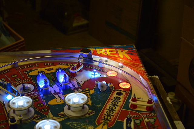
As I stated; been working on the cabinet for the Mirror universe project. I bought a couple of “project” Bally Star Treks from a fellow pinball collector out of Shertz a few years ago. These have been setting in storage for a while… and were very rough.

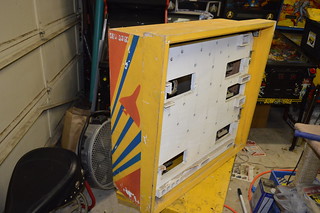
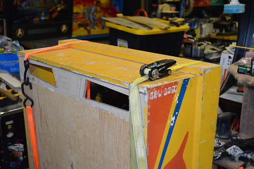
I took the cabinet with the most flaking and damage as the donor cabinet for this project. Here it is in all it glory:

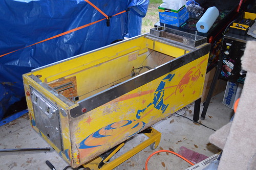
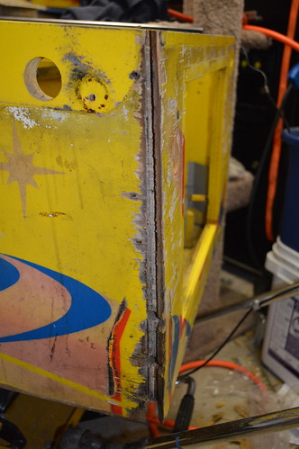
I began by stripping all the hardware (coindoor) and side rails off of the machine so I could access the state of the “bones” (ie wood) of the cabinet. I noticed that the front corners were beginning to separate…. also some of the plywood cores were starting to come apart.

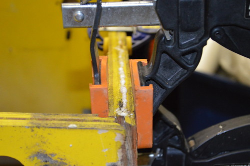
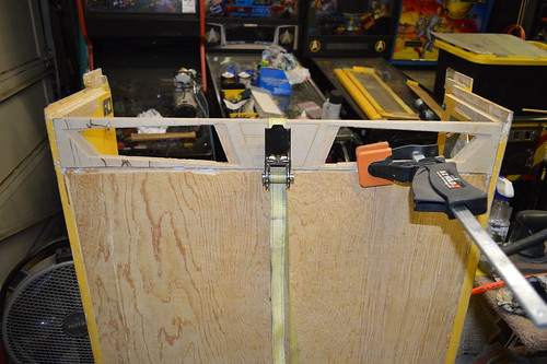
First I used some white gorilla glue to repair the plywood core:

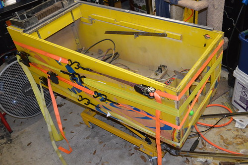
Then I used ratchet straps to re-glue both sides:

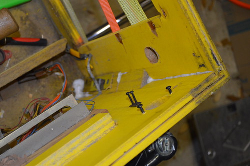
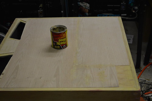
I CNCed a diamond shaped piece out of MDF and glue it in the old shooter hole:

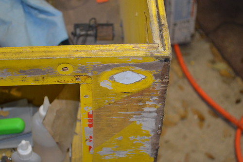
With that I began stripping the old flaking paint off with CitraStrip along the way I tried to save as much of the wood as I could. When possible; I reglued the laminate back to the plywood… or used some wood filler to fill in the rough areas.

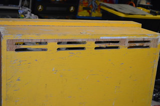
I also repaired the bottom – not pictured. 3 of the four sides had lost the plywood under the grove… which means the bottom would probably fall out at some point. I fixed this by saving as much of the plywood core on the 1 “acceptable” side… then using quarter round pieces from Lowes. The quarter round piece was secured with the same gorilla glue and some 18 gauge pin nails.

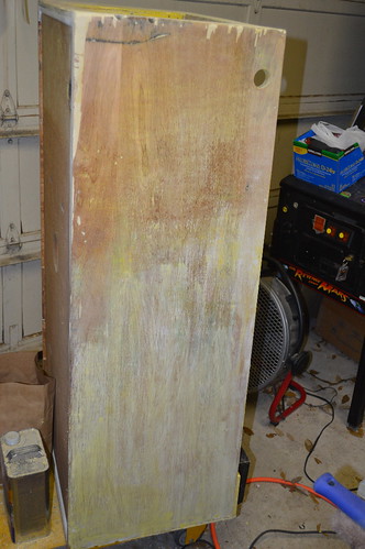
I bought some mill wax ebony oil stain as I wanted to stain the cabinet black instead of paint. I wanted something “different” looking. Here’s one side stained with several coats. Looked like absolute trash…

That just would not do AT ALL.

The next day I went to our local WoodCraft store … they seemed to have a better selection of stain.

Since I was in new territory on this project; I decided to get a couple of product. The first was a Ebony Wood Dye product and the second was a Black Water-based Stain. The guy at the store claimed the dye would dye the fibers of the wood in a “molecular” like fashion … while the Stain is pigment based (and would act more like paint). I added the later. I figured I’d buy both and try it on the cabinet.

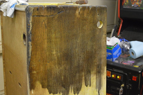
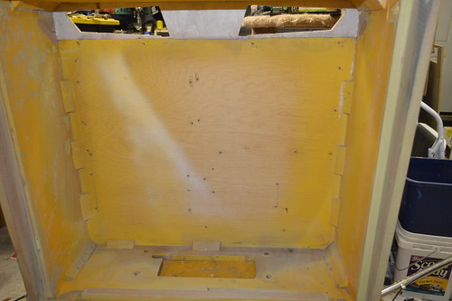
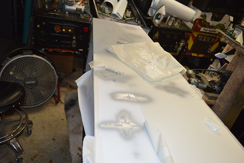
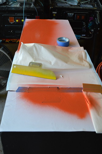
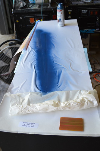
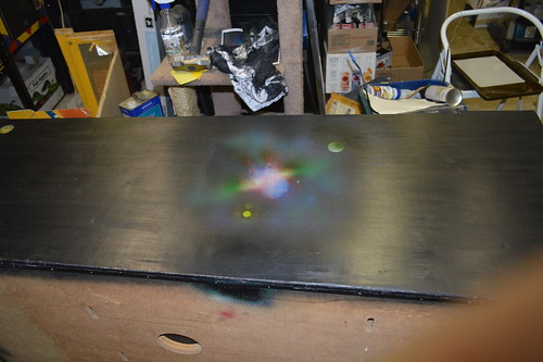
After I got home; I stripped the back of the cabinet and put down some test swatches:

Upper right hand: Ebony Dye
Upper LEft: Satin Black Stain
Lower Right: Stain over Dye
Lower left: 50/50% mix of both

I didn’t like the ebony stain as is… as it still had a purple/blue hue to it. The stain looked ok; but had a paint like view. The Dye under Stain had what my mind thought was the best of the two. The Dye in effect raised the wood grain a little; and the stain still let the overall look like a satin look. The 50/50 worked; but wasn’t as vibrant as the Stain over dye.

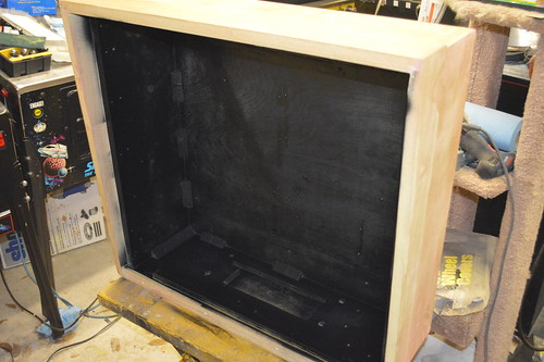
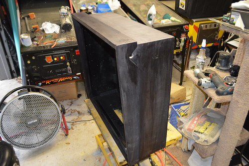
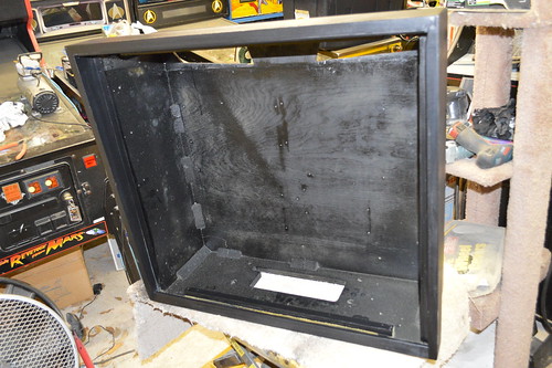
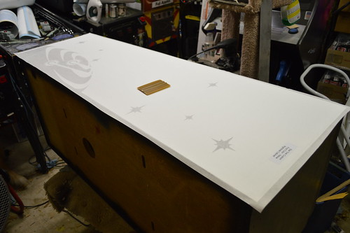
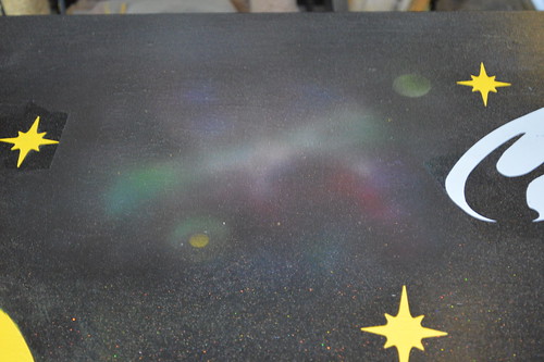
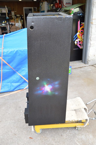
With this decision; I proceed to dye then stain the cabinet. The outsides of the cabinet were stripped of all paint; then dyed then stained. The inside of the cabinet I decided to lightly sand the interior then spray it with a Satin Black spraypaint from Rustolem. I also sprayed the bottom side with the same Satin black so it’d look more finished.
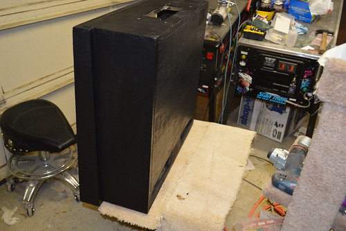
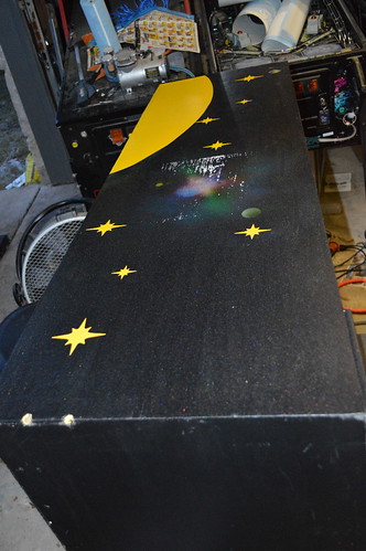
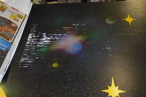
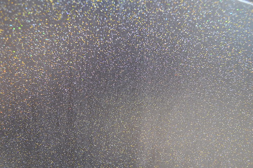
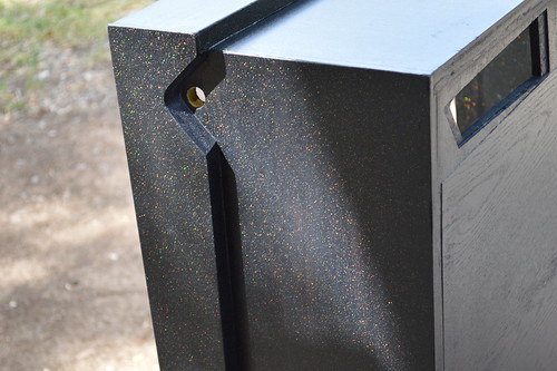
The results:

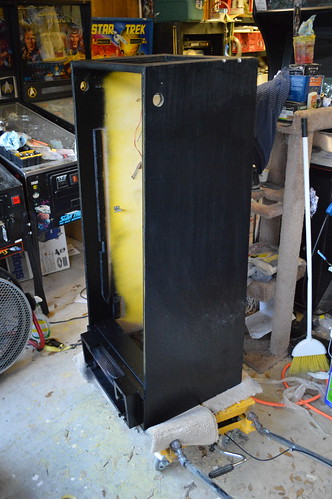
Yes… I probably could have save myself some more time by just painting the cabinet with some latex black… Or any black paint; but I kinda wanted to have the wood grains show thru the background. I may regret this decision later… but I’m currently very happy with the way it turned out.

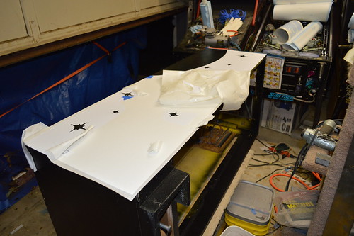
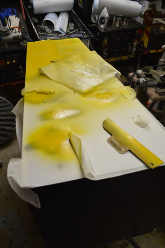
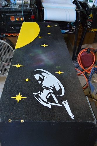
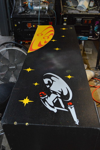
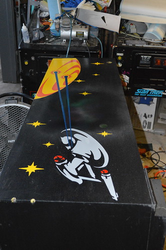
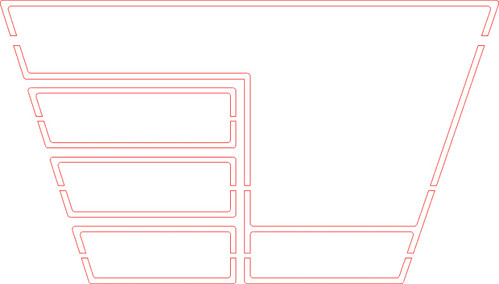
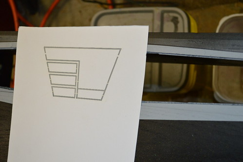
Tonight I worked on the stencil design for the cabinet. Obviously; it’s going to be a black background; however, I wanted to pay a nod to the original cabinet design. I traced the existing design and pulled it into Corel Draw. Given Black background; I still wanted to keep some of the same colors in the stencil. So the stars became Yellow. The planet Yellow/Red… and The Phasers became blue. I going to make the Enterprise BattleShip grey.

I removed the Klingons … instead having the Enterprise fire on the planet. 😀

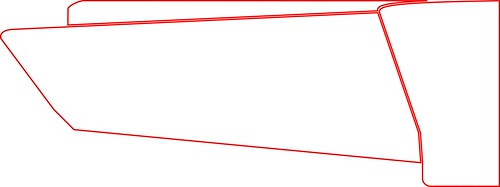
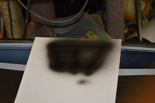
I also worked on the front art; “inverting” the shooter location and making the color scheme similar to the sideart.

Not sure about the text at the bottom. Again limited by a stencil; but need to look at this further.

The Head: I’m thinking about keeping the Head design the same… but change the blue background to black.

After visiting with Modders-inc.com at Quakecon 2013, Lockman, MrRed, and I picked up a donor head from DonW in Garland. Don graciously donated this head to the Mirror Universe project.

It started life as a Supersonic head… and was a rough from a paint flaking/ding perspective. All of this mattered nothing to me… as it was going to be dye/stained black just like the cabinet. Here are some before shots of the head:

The back vent hole were coming apart; good because I wanted to improve the ventilation anyway…

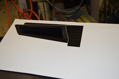
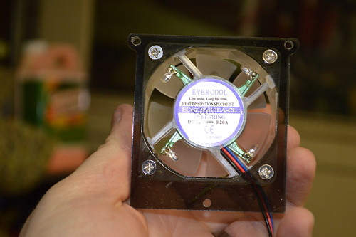
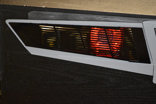
I went about destructing the head… to create new vent holes. Since eventually I plan to put more than just the original boards in the head… I decided I wanted some active cooling (IE DC FANs)… What better way to integrate vents… but using something from the Enterprise.

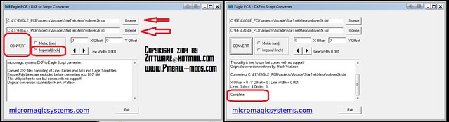
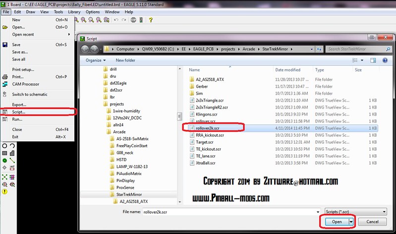
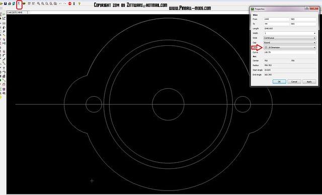
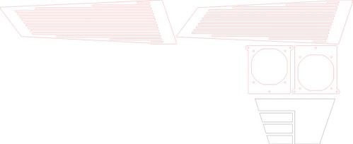
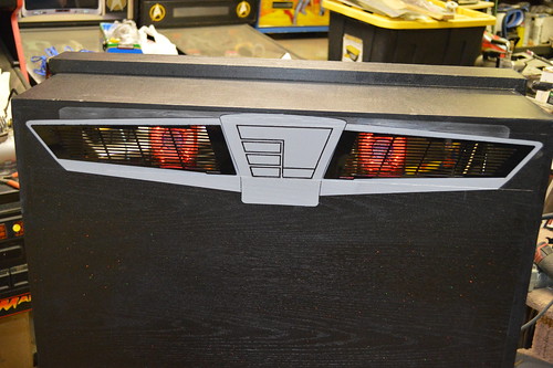
Using the great work by colosseumbuilders.com; I recreated the Enterprise’s impulse engines in CAD using the following as a guideline:

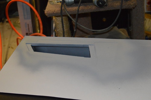
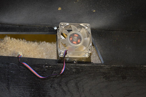
The resultant CAD file yielded the following rendering of the DXF file. In order to practice for the upcoming Playfeild CNC work; I wanted to practice with by CNCing out these vent holes in the Russian Plywood. Ken and I went to Techshop.ws this past Saturday and CNCed the back vents:

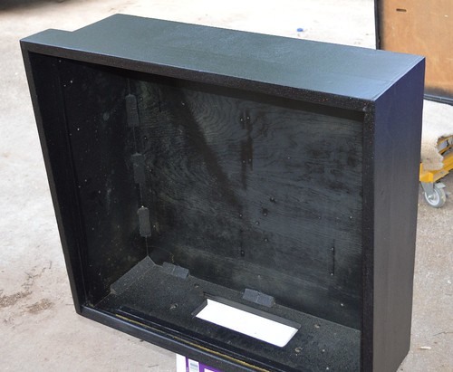
Once I got home; Saturday night I began re-assembling the head:

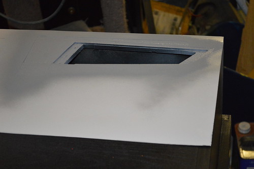
Then I lightly sanded and vacuumed the inside of the head to prep it for interior paint:

This time I decided to paint the inside prior to staining the outside; so:

After the interior dried; I needed to replace the Veneer which I removed during the deconstruction phase.

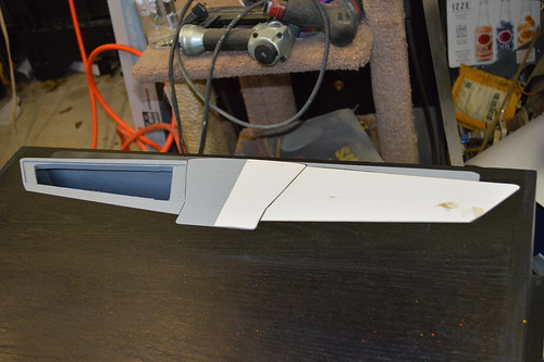
I thought about going to woodcraft to get it; but really; I didn’t want to drive 30minutes in traffic… so I opted to get the iron-on type from Lowes. It comes in a roll; and you melt the glue with an iron.

The smaller roll of veneer was on clearance; so I opted for it… but turned out to be a hair short. I filled the seams with Plastic Wood filler so the seams wouldn’t be visible on the back without a close inspection.

Not sure what I’m going to do about the small section… worst case I’ll apply a patch after-the-fact.

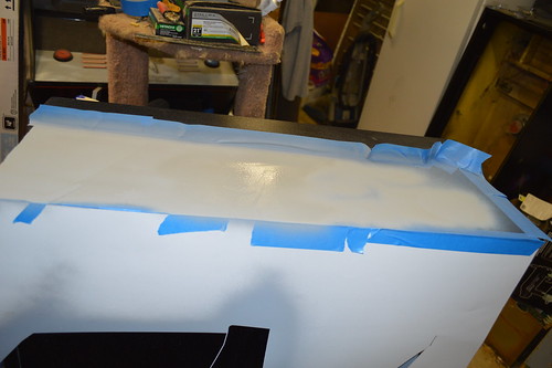
After some lite sanding with the orbital sander the back and the head was ready for the Black Dye:

followed by the Black Stain:

Even the bottom didn’t escape the black of space…

The plan is to let the Stain/Dye cure overnight. Then I’ll begin to spray the Polycrlic Satin clear coat over the stain to seal the wood and prep is for future Stenciling.

My head did not come with any of the metal trays for the displays… if anyone is parting out a early 80s Bally Solid State machine… I’d very much appreciate the opportunity to obtain these trays for my Nixie tube displays. Please post a comment or email me. Thanks!